
From a DXF taxiway network to fillets, markings, stands and paint quantities.
AirfieldIQ reads the whole taxiway and runway network from one DXF, sets widths and clearances from the design aircraft fleet, designs the junction geometry and markings to Annex 14, lays out aircraft stands, and quantifies the paint.
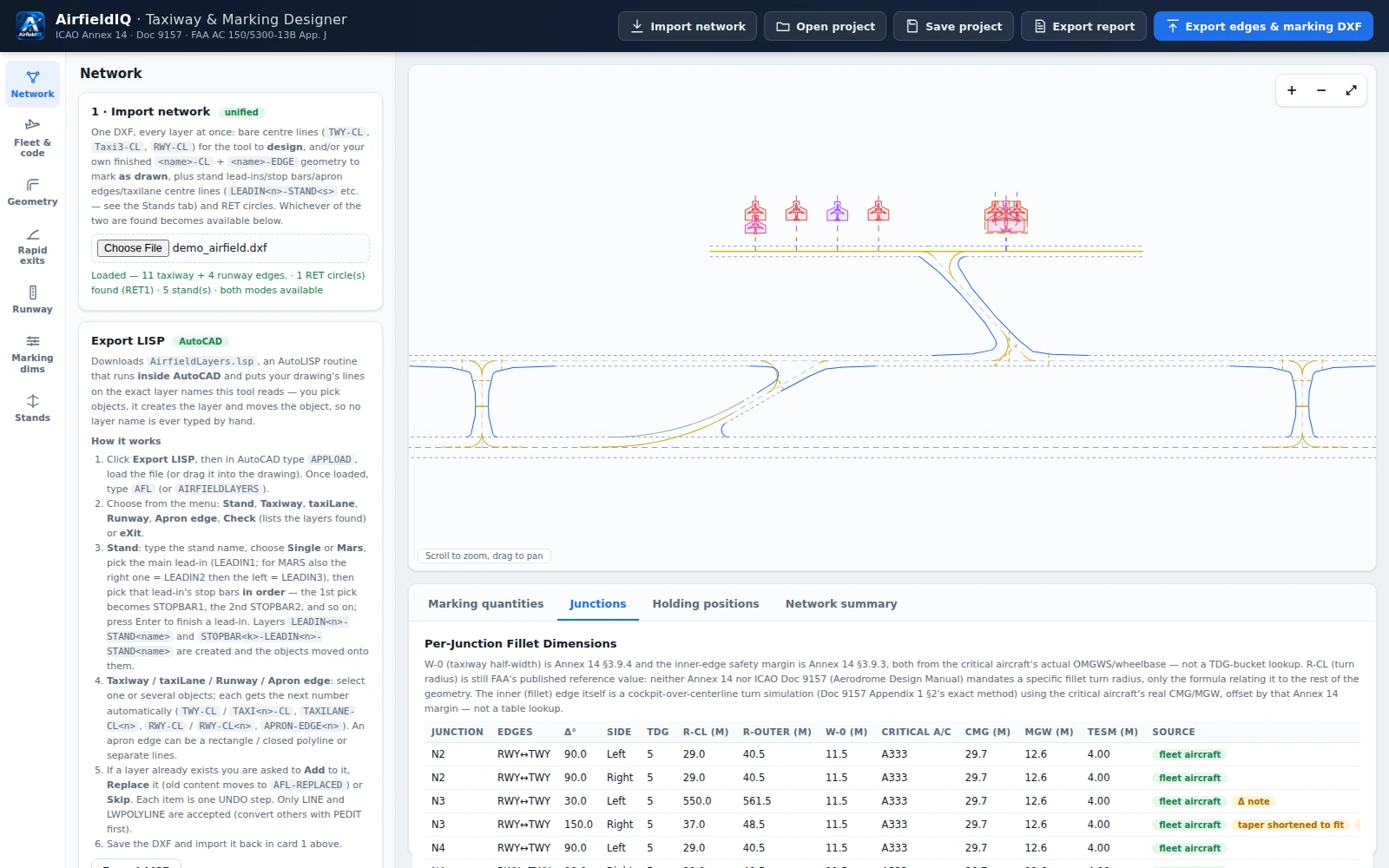
Built around the network, the aircraft and the markings.
The whole network from one DXF
Import multiple junctions, links and runways from a single drawing. An exportable AutoLISP routine assigns the layers the tool reads.
A design basis driven by the design fleet
The design aircraft fleet sets the TDG, code letter and the required widths and clearances automatically, with manual override. Runway code number and type, instrument status and the runway-holding position distances follow Annex 14 Tables 3-1 and 3-2.
Fillets, curve radii and a swept-path check
Fillet and centreline curve radii at every junction (R-Fillet, R-CL, R-O) per aircraft, with typed minimums and per-junction dimension tables. A swept-path check follows the design aircraft along the taxiway.
Rapid exit taxiway locations
A location calculator driven by threshold speed classification, tailwind and slope, with the segment-by-segment calculation shown. Add RETs by distance, side and exit angle, or read them from DXF circles.
Markings to Annex 14 §5.2
Runway and taxiway markings, including holding positions and the taxiway and runway centreline curves, with editable marking dimensions.
Aircraft stands, MAX SPAN and ERL
Place aircraft on stands with lead-in lines, stand ID, MAX SPAN wing-span limit markings and equipment restraint lines (ERL) along the apron edge, with taxilane and apron-edge handling.
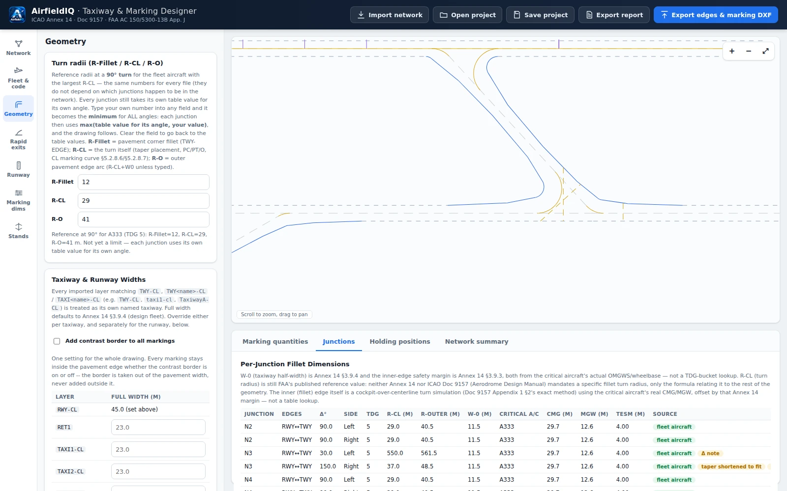
Fillet and centreline radii at every junction, per aircraft.
Set the turn radii for the design fleet, and each junction takes its own table value for its angle, with the per-junction dimensions listed and sourced.
- R-Fillet, R-CL and R-O per junction
- Typed minimums applied across all angles
- Dimension table with the source of every value
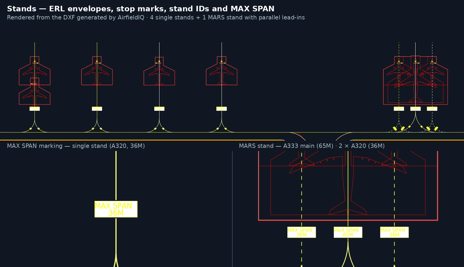
Stands laid out on the apron, aircraft by aircraft.
Each stand takes its lead-in line from the drawing, one or more aircraft types, and its own display ID, with the apron edge and taxilane connection detected automatically.
- Single or multi-aircraft stands (for example MARS)
- Lead-in clearance and flip direction per stand
- MAX SPAN and equipment restraint line markings
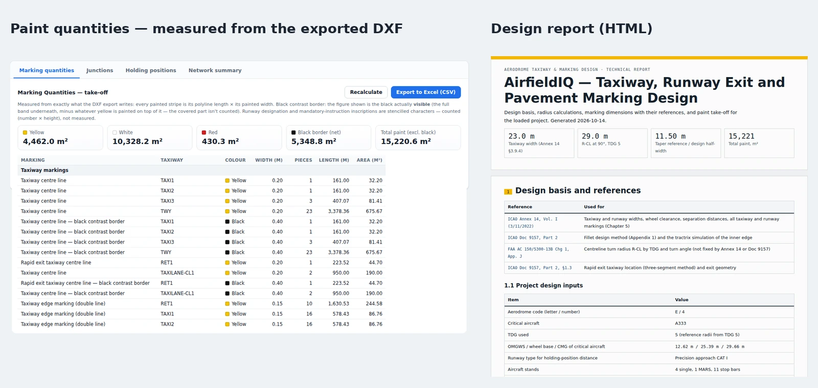
Design output you can hand to a contractor.
The same model that draws the markings also quantifies them, so the numbers and the drawing never drift apart.
- Marking quantities (paint areas, take-off and landing) exported to Excel (CSV)
- DXF with all geometry and markings on named layers
- A full design report with the basis and references, widths and separations, radii, RET, taxilanes and apron edges, markings, stands, paint quantities and open points
- Project save and load (JSON)
Watch a taxiway network become markings, stands and paint quantities.
Runs in the browser. Nothing to install.
Server-side calculation engine
The design logic runs on the server, so there is nothing to install and the calculation engine stays protected.
Secure sign-in with an emailed one-time code
No passwords to manage. Enter your email, receive a six-digit code, and sign in. Not sure yet? Start with a 3-day pass.
Standards-referenced, printable results
Every result cites the standard it follows and feeds a design report you can print or save as PDF.
Take a real taxiway network through AirfieldIQ.
Try it with a 3-day pass, or request a demonstration and bring your own DXF.